Friday, November 20, 2015

Friday, Nov 20th, 2015 Part 2 - canopy, wiring, headset jacks, fuel selector, misc

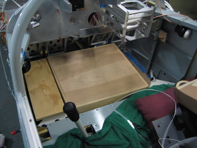
I've been wanting to come up with something that will allow me to lay down under the panel semi comfortably rather than bend backwards onto the floor.  If nothing else this would be handy for when I have to rivet the forward top skin.  I decided to see if it was possible since I wasn't sure if I got it level if I'd fit in the remaining space.

I have a couple of stands I've been using that are about 7" high that once again came in very handy.  One of them was just about the perfect height and nicely straddled the center section where the wiring and fluid lines go.  I fabbed up a small shoebox sized stand to fill the gap on the side and this was the result.  Covered it with a sheet of cardboard and put a small blanket over it and it worked great.  It's very tight, but will probably serve well for riveting.

From Finish Kit 2

On my last order from Aircraft Spruce I picked up some grommet edge.  I'd been making my own out of split nylon tubing - worked ok but I really wasn't too happy with it.  This stuff is great - it has a metal core that is very grippy and will not come out.  This is the passthrough for the Dynon D10.

From Finish Kit 2

Passthrough for the Skyview connector gets the same treatment.  The black box on the back side is the Dynon ARINC box.

From Finish Kit 2

While I was at it I installed an 8 slot fuse block.  There weren't enough CBs in the VPX sport to handle every connection, but the VPX Pro was overkill for me.  The solution is to hang a fuse block off of one appropriately sized CB on the VPX, then size the fuses in the block for the various loads.  This will power non essential items like panel lights, primer solenoid, etc.

From Finish Kit 2

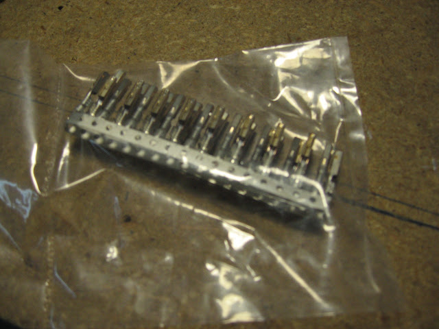
Installed a molex connector on the flap power lines to allow removal if necessary.

From Finish Kit 2

Detail of the other end of the connector.

From Finish Kit 2

Safetied the flap pushrod to the bolt per the plans.  Hopefully this will be the last time I will put this together.

From Finish Kit 2

Enlarging the hole in the fuel selector bracket to accept the Andair fuel selector.

From Finish Kit 2

This is what the Andair fuel selector valve looks like.  Really high quality unit.  The fittings are clockable and are available in a wide variety of sizes and types.  I'm installing the nutplates.  The holes for the nutplates as well as the dimples are all pre-machined.  The slots in the center section are where the lockout button goes.  You *cannot* turn this valve off by accident.  There is a spring loaded pin on the handle that has to be positively lifted and then the handle turned.  The single hole on the back center is the hole for the locked off position.

From Finish Kit 2

There is a pre-drilled and labeled trim piece that fits on top of the selector mount.  Used it to mark out the holes for drilling.

From Finish Kit 2

Detail of the fittings.  O-rings on the inside give a positive seal, and the allen screws are staked after tightening to ensure they don't back out.

From Finish Kit 2

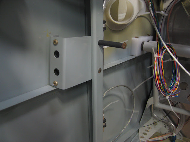
Running the pitot heat and landing light wires to the terminal block under the pilot's seat.  The left side passthrough is so full you can't get one more wire through it, so these will run through the center.  Still have a bit of room on that one.  Hopefully it's enough.

From Finish Kit 2

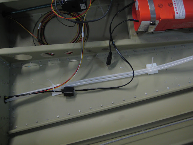
It may not seem like it, but I'm actually making progress.  I think I've pretty much figured out where everything will go and how it will be routed, so now I'm starting to tie off the unused wires, then run and terminate the grounds.  The final bit will be to terminate the power lines.


From Finish Kit 2

I got a note from Amy at Flightline that she's done with my seats.  I should be getting those and the carpet from her early next week.  :)  Looking forward to seeing what they look like.

Thursday, November 19, 2015

Thursday, Nov 19th, 2015 Part 1 - canopy, wiring, headset jacks, fuel selector, misc

This is going to be a two part update - I've been doing a lot of stuff but just haven't taken the time to update the blog.  Too many pictures for a single post, so I'll break it into two parts.

Installed the Skyview and D-10 in the panel so I could figure out where to run the wires.  There is a large (37 pin) connector on the backside of the Skyview, as well as a couple of USB connections and 9 pin DSUB connectors for the network connections.

I need to find a place to put the EMS box and the ARINC box.  Based on where the wires are going, it looks like the back side of the sub panel will be the best place.

From Finish Kit 2

I decided to put the ARINC box catty corner behind the center sub panel.  Cut 2 holes for cables to pass through.  The large one on the lower right is for the large Skyview connector.  The smaller one is to bring the network connections from the ARINC and EMS boxes.  I've got a Dynon network splitter that will allow connecting them together and will reach through to one of the DSUB connectors on the Skyview.  If I haven't forgotten something, I won't need another hub.  The connection from the hub in the back runs through the center passthroughs and will connect to the other network connection.

From Finish Kit 2

Finally was able to confirm that the plug in the top of the carb is for the temperature sensor, so I installed the carb temp sensor from the EMS sensor pack.

From Finish Kit 2

Since the tach info will come from the Emags, I need a cover for the tach attach point.  Andair makes one, so I picked that up and installed it.

From Finish Kit 2

I've been putting off doing the final riveting on the canopy for nearly a year.  Dreading possible cracking after reading all the problems people have had.  I've left it clecoed for at least 6 months.  Did a final check of everything and started riveting it with the pulled rivets.

From Finish Kit 2
It's really odd not to see all the clecoes sticking out any more.  The part I was most worried about was the forward bend.  I had a lot of problems getting it to fit when I first started working on it.


From Finish Kit 2
Finished and no cracks.  Big sigh of relief.

From Finish Kit 2

Detail of the back .  Pretty happy with how this came out.

From Finish Kit 2

Since I have to do something with the headset connectors before I go too far with wiring the radio stack, I decided to tackle where I was going to put these.  I've seen a lot of good solutions, from just putting them in the lower left of the panel or on a subpanel on the lower flange, to putting them in the forward angled canopy deck.  I've also seen them in the seat pans or back bulkhead behind the pilot/passenger. None of those really got the cables out of the way the way I wanted to.

Kent Stitt had his behind and below the panel on a small bracket.  Really liked that solution, so I mocked it up from some scrap aluminum to see how that would look.  I sat in the cockpit for several hours trying this out and decided to go this way, although I ended up moving the bracket above the horizontal angle instead of below as it is here.

From Finish Kit 2
I tried a couple of times to get satisfactory bends for these brackets, and couldn't produce anything I liked, so I picked up one of the cheap brakes at Harbor Freight.  I fiddled around trying to make something and quickly realized anything I could cook up would cost as much or more than this and probably wouldn't be as good as this one.

The way this works is it's hinged in the middle and folds upward using the handles.  There is a heavy steel (1/4" maybe) top piece that you can see sitting on the back top of the brake.  The material you want to bend is placed between the top piece and the brake, with the bend line along the hinge line of the brake and clamped into place with c clamps or similar (not provided, but I have plenty).  The top clamped piece has one edge milled to 90 degrees and another that's been milled at a bevel (20-30 degree maybe).  I got the best bends with the bevelled edge.

From Finish Kit 2
Test bends.  One is a factory angle, one is mine from scrap sheet.  Nearly identical.  One change I made later was to stick a long #40 drill bit against the bevel (on top of the material I'm bending).  That created a nearly perfect radius on the bend.

From Finish Kit 2

Comparison of the factory angle and one I did.  Mine is on the bottom.

From Finish Kit 2

Here's the final headset bracket.  I decided to make it in two pieces so I could remove it if needed.  The edge that goes against the outside will be dimpled and riveted to the skin.  Nutplates on ears will hold the larger piece.  Back edge gets nutplates to attach to the stanchion.

From Finish Kit 2

Final product.  I'll drill through the upright stanchion and the bracket to attach the back edge.  A long top bolt at the top will make a nice headset hanger.

From Finish Kit 2
Picked up some lugs and insulating nipples from Stein for the larger wires.

From Finish Kit 2
Also picked up some of the Vertical power power connectors.  These dudes are pricey.

From Finish Kit 2

Fabricated the #2 cable for the starter and ran it down the right side (#1 cylinder side) of the engine.
This was my first attempt at hooking up the manifold lines.  Not at all happy with this.  Way too many connections and just too cheesy.  The manifold line from the #3 cylinder comes in from the left here, the two vertical tubes are for the Emags, and the right fitting on vertical manifold will go to the Dynon sensor.

I later called Tom Swearingen at TS Flightlines and had him make me up a long manifold line to just go the full distance from the cylinder to the vertical manifold.  I can easily connect the Emags to the third hole using a tubing fitting later.

From Finish Kit 2
Marking the headset bracket for drilling to the stanchion and skin.

From Finish Kit 2
Painted and installed.  There are nut plates on the bracket behind the stanchion.  Used an AN3-22 bolt at the top with aluminum tube and heat shrink tube over it.  Makes a nice holder for the headset.

From Finish Kit 2

Wednesday, September 9, 2015

Wednesday, September 9th, 2015 - catchup update - mostly wiring

Big catch up update since I haven't posted anything in way too long.

Finished up the ammeter shunt and ANL fuse mounting.  Just used a big copper bus bar to jumper the shunt to the ANL fuse block and the ANL to the contactor.

From Finish Kit 2

I ditched the Van's primer tubing and fittings since I didn't like it, and purchased and installed the ECI Titan primer system (everyone tells me I won't need it, and I probably won't use it much, but if I'm out somewhere where I'm in colder temps and can't pre-heat, it may be the only way to start, so I'm installing one).

These are some pics of the install.  Tubing is shipped in nice protective plastic tubes and is all to length with an installation diagram.  I started at the cylinders and worked back.  Plumbed all but #3.

From Finish Kit 2


From Finish Kit 2

The straight tube going aft is not permanent, I just mounted it temporarily so I could get some leverage to bend everything to fit.

From Finish Kit 2

#1 cylinder tubing.  I'll add a pair of adel clamps around the intake tube and primer line to secure it.

From Finish Kit 2

#2 and #4.

From Finish Kit 2

The Titan kit uses stainless lines (very nice) but has a weird ball fitting on the ends I hadn't seen before. After googling around they turned out to be a "Union Cone". Talked to Tom at TS Flightlines and he said he can fabricate a flex fitting from a standard AN-2 to a Union Cone, so I'll do that.

The AN800-2C in the picture below (from Aircraft Spruce) shows what one looks like - they are silver soldered or braised onto the stainless primer lines.


Fabbed a mount for the primer solenoid (Van's) and installed it above the gascolator, then used some of the stuff from the Van's kit to plumb it to the Andair gascolator primer port.


From Finish Kit 2

Also noodled around looking at how to do the "Red Cube" fuel flow sensor. Finally decided to mount it between the gascolator and the engine driven pump.

Need to get hoses and more fittings for that as well. Worked on how to plumb the manifold pressure sender but still haven't decided for sure. Probably use the flex hose from Van's and hook that to aluminum tube on the firewall with AN fittings then switch to a 1/4" NPT with a hose fitting for the Dynon sender since it has a hose fitting on the sender.

After that I started running all kinds of wires.

A/P servo, Skyview network cable and ADAHARS wired to the mid fuse hub I installed. The Smaller bundle of loose wires is the A/P servo.  The network part of the roll servo wiring will come back here as well.  That will leave one open port on the hub - plan to use that for the ADS/B unit when I get it, which will be installed back here on a panel similar to the one used for the hub.  Antenna will just go through the aft fuse floor.

From Finish Kit 2

A/P servo power and disconnect wiring runs forward separately.

From Finish Kit 2

Added cable clamps down both sides of the elevator pushrod tunnel to secure all the wiring.

From Finish Kit 2

Same deal on the left side - fat black cable is the manual elevator pitch control cable.

From Finish Kit 2


AOA and Pitot tubing runs from the ADAHRS in the tail forward. Also used the same run for the ELT control wiring and the A/P servo power.


From Finish Kit 2

Pitot tubing, A/P servo power and ELT control wiring just aft of the baggage wall.  Orange box is the 406mhz ELT.

From Finish Kit 2

Starting to accumulate a rat's nest of wire where I'm leaving it long until I figure out exactly how it will route and terminate.


From Finish Kit 2

Installed adel clamps along the upper angle on the aft side of the firewall to secure wiring.

From Finish Kit 2

Cut the heat box control cable to length and installed it.

From Finish Kit 2


Decided to install a terminal block under the pilot's seat to provide an easy disconnect area for wing and aft wiring. This won't get it all, but will cover pitot and landing light ground, strobe & nav light power and sync, and pitot and landing light power.


From Finish Kit 2

Terminal block partly labeled and strobe wiring terminated and installed.


From Finish Kit 2


Installed the "forest of grounds" (B&C) on the upper right firewall above the battery box.


From Finish Kit 2


Forward side of the grounding tab block.


From Finish Kit 2


Drilled a hole in the upper left (pilot) side firewall to install the passthrough for the EMS wiring. Using the 3/4" unit - at first I thought I'd gone too small but I was able to get everything through pretty easily including the inner wrapping of slit fire sleeve.


From Finish Kit 2


Ran all the EMS wiring through, then identified and labeled each line.


From Finish Kit 2


I picked up one of the Rhino (Dymo) labelers and love it. I've run through a whole cartridge of 1/4" heat shrink and ordered two more. Works great. Amazon had it for only $35 or so. Well worth it. Used that to label all the EMS wiring.

Once I'd done all that I decided it was time to do an avionics location mockup part deux to do a sanity check on locations and to try to start to finalize wiring routing.

As mentioned before, VPX-Sport is upside down between the forward upper ribs.  EMS at the moment is behind the sub panel on the left (pilot's) side forward of the D-10.

From Finish Kit 2

Trying the ARINC behind the middle sub panel.  I need to put a passthrough hole in the sub panel to run the main wiring for the Skyview.  That will probably be just under the middle rib.

From Finish Kit 2

Trial fitting the transponder on the upper inside of the right rib.  This location actually seems to work pretty well but I'll leave it for a few days to see if I see any obvious problems with it.

From Finish Kit 2

Fast stack location finalized behind and under the glove compartment (which will be removable).  Cable routing works really well and I can install cables from forward pretty easily.

From Finish Kit 2