Rebecca wanted a new desk (she'd been using a really old computer desk I built about 30 years ago, and was tired of it), so I took about 4 days to do that. I'll try to post a picture if I remember to take one.
Once the main gear weldments are mounted, Vans wants you to install the wings. They do mention an option to do one at a time (not real inclined to do that since I want to make sure they are square not only to the fuse but to each other).
Anyway, the more I looked and thought about it the more it made sense to me to do the vent, fuel and brake lines first, since they have to attach to the wing, and there is little or no room to work if the wing is on.
I did do it that way, and it seems to have worked out for the best. I didn't ruin any tubing, and there was more than enough to leave extra on the free ends where they will attach to the tanks.
First thing I did was start on the vent line. It looked like it would be easier, and give me a chance to get used to working with aluminum tubing, doing the bends and flares, and generally just getting the hang of things with a relatively easy part.
First one I did was the right vent line.
There is a bulkhead fitting through the bulkhead. I decided to start there, then work up and forward.
I used a 90 degree tubing bender I picked up at Home Depot to do some of the bends. Once you get the hang of it it works fairly well, although figuring out where to start the bend so you'll end up where you want is a bit trickier. I tend to err on the "too much" side then trim back if need be.
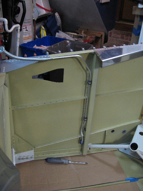
I used the bender to put in the curve where it needs to clear the rudder cables. Adel clamps are used to hold the tubing along the bulkheads.
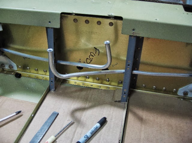
The other "tool" I ended up using even more is a spring tubing bender - you can just make it out in the lower photo. This allows you to make free form and complicated bends pretty easily, and the spring will make the tubing keep its shape so it does not collapse.
The box on the floor next to the tubing has all the AN fittings - these are mostly flared fittings for the fuel and brake systems. The hardware is all aluminum, but is anodized, which is why it is all blue. The flared fittings are 37 degrees.
Once the tubing is to the right length, it is trimmed, squared, deburred, then flared with a flaring tool.
Here's the flaring tool - Parker Hannifin I got from Aircraft Spruce.
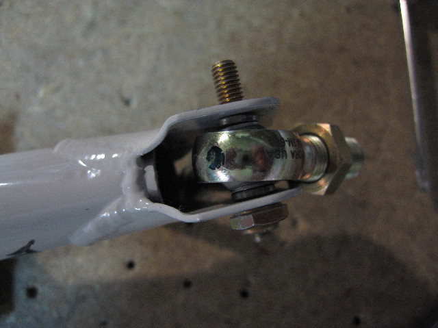
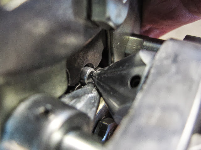
Here's a close up when I'm doing a flare. There is an index piece incorporated with the clamping mechanism - with it open, you run the tube up against the index and that will ensure the tubing is in the proper place relative to the die and (mandrel? not sure what the flaring part is called...). You can see the tubing in the center held by the dies.
Finished flare - all aircraft flares are 37 degrees, unlike cars which are usually 45 degrees.
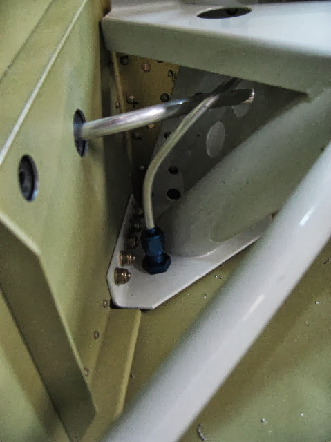
Here's the completed right side vent line. The vent fitting exits through the floor and is angled forward to catch the slipstream and force air into the tanks.
Left side is a mirror image of the right.
The last part of the vent line is to make the short tube that exits through the fuse side to attach to the fuel tank vent fitting.
Once I did those, I started on the fuel lines, which are 3/8", so quite a bit heavier and stiffer to bend.
I came up with a useful technique for running the lines. I bent and flared the inboard ends first (notice something missing??? argh!), then ran the tubing outboard. I installed my spring tubing bender with a curve that led the fuel line out through the gear weldment hole. The fuel line just slid right through, bending as it went. Much easier than trying to bend, push, bend around the corner and out through the side.
By the way, it's easier if you take the bushing out and tape the hole so the tubing won't abrade on the way out.
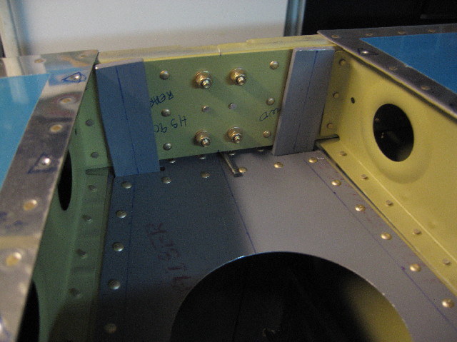
Fuel lines done - test fitting the Vans supplied fuel selector.
I'm still
Working on the right brake line. I used the spring tubing trick here as well. *Much* easier.
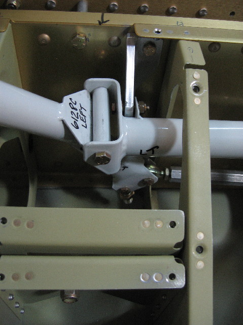
Running the right brake line forward through the center section.
Labor Day Becca helped me install the wing. I'm not drilling anything, just test fitting and running through the tasks Vans spells out. At first it was hard to get going, but I realized I was hung up on the rear spar bracket and bottom skins. Once I got those sorted out it went fairly well. There is more dihedral than I thought.
Probably spent 30 minutes getting the wing on. I'm sure next time it will go much quicker. Fuel tank is not installed in this pick.
Rear spar attach. Looks like I have plenty of edge distance.
Fuel tank installed. Starting to look like an airplane. :)