Finished up the ammeter shunt and ANL fuse mounting. Just used a big copper bus bar to jumper the shunt to the ANL fuse block and the ANL to the contactor.
 |
| From Finish Kit 2 |
I ditched the Van's primer tubing and fittings since I didn't like it, and purchased and installed the ECI Titan primer system (everyone tells me I won't need it, and I probably won't use it much, but if I'm out somewhere where I'm in colder temps and can't pre-heat, it may be the only way to start, so I'm installing one).
These are some pics of the install. Tubing is shipped in nice protective plastic tubes and is all to length with an installation diagram. I started at the cylinders and worked back. Plumbed all but #3.
 |
| From Finish Kit 2 |
 |
| From Finish Kit 2 |
The straight tube going aft is not permanent, I just mounted it temporarily so I could get some leverage to bend everything to fit.
 |
| From Finish Kit 2 |
#1 cylinder tubing. I'll add a pair of adel clamps around the intake tube and primer line to secure it.
#2 and #4.
The Titan kit uses stainless lines (very nice) but has a weird ball fitting on the ends I hadn't seen before. After googling around they turned out to be a "Union Cone". Talked to Tom at TS Flightlines and he said he can fabricate a flex fitting from a standard AN-2 to a Union Cone, so I'll do that.
The AN800-2C in the picture below (from Aircraft Spruce) shows what one looks like - they are silver soldered or braised onto the stainless primer lines.

Fabbed a mount for the primer solenoid (Van's) and installed it above the gascolator, then used some of the stuff from the Van's kit to plumb it to the Andair gascolator primer port.
Also noodled around looking at how to do the "Red Cube" fuel flow sensor. Finally decided to mount it between the gascolator and the engine driven pump.
Need to get hoses and more fittings for that as well. Worked on how to plumb the manifold pressure sender but still haven't decided for sure. Probably use the flex hose from Van's and hook that to aluminum tube on the firewall with AN fittings then switch to a 1/4" NPT with a hose fitting for the Dynon sender since it has a hose fitting on the sender.
After that I started running all kinds of wires.
A/P servo, Skyview network cable and ADAHARS wired to the mid fuse hub I installed. The Smaller bundle of loose wires is the A/P servo. The network part of the roll servo wiring will come back here as well. That will leave one open port on the hub - plan to use that for the ADS/B unit when I get it, which will be installed back here on a panel similar to the one used for the hub. Antenna will just go through the aft fuse floor.
A/P servo power and disconnect wiring runs forward separately.
 |
| From Finish Kit 2 |
#2 and #4.
 |
| From Finish Kit 2 |
The Titan kit uses stainless lines (very nice) but has a weird ball fitting on the ends I hadn't seen before. After googling around they turned out to be a "Union Cone". Talked to Tom at TS Flightlines and he said he can fabricate a flex fitting from a standard AN-2 to a Union Cone, so I'll do that.
The AN800-2C in the picture below (from Aircraft Spruce) shows what one looks like - they are silver soldered or braised onto the stainless primer lines.
Fabbed a mount for the primer solenoid (Van's) and installed it above the gascolator, then used some of the stuff from the Van's kit to plumb it to the Andair gascolator primer port.
 |
| From Finish Kit 2 |
Also noodled around looking at how to do the "Red Cube" fuel flow sensor. Finally decided to mount it between the gascolator and the engine driven pump.
Need to get hoses and more fittings for that as well. Worked on how to plumb the manifold pressure sender but still haven't decided for sure. Probably use the flex hose from Van's and hook that to aluminum tube on the firewall with AN fittings then switch to a 1/4" NPT with a hose fitting for the Dynon sender since it has a hose fitting on the sender.
After that I started running all kinds of wires.
A/P servo, Skyview network cable and ADAHARS wired to the mid fuse hub I installed. The Smaller bundle of loose wires is the A/P servo. The network part of the roll servo wiring will come back here as well. That will leave one open port on the hub - plan to use that for the ADS/B unit when I get it, which will be installed back here on a panel similar to the one used for the hub. Antenna will just go through the aft fuse floor.
 |
| From Finish Kit 2 |
A/P servo power and disconnect wiring runs forward separately.
 |
| From Finish Kit 2 |
 |
| From Finish Kit 2 |
Same deal on the left side - fat black cable is the manual elevator pitch control cable.
 |
| From Finish Kit 2 |
AOA and Pitot tubing runs from the ADAHRS in the tail forward. Also used the same run for the ELT control wiring and the A/P servo power.
 |
| From Finish Kit 2 |
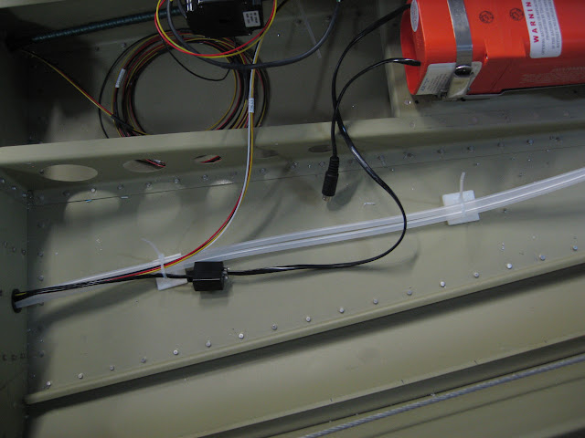
Pitot tubing, A/P servo power and ELT control wiring just aft of the baggage wall. Orange box is the 406mhz ELT.
 |
| From Finish Kit 2 |
Starting to accumulate a rat's nest of wire where I'm leaving it long until I figure out exactly how it will route and terminate.
 |
| From Finish Kit 2 |
Installed adel clamps along the upper angle on the aft side of the firewall to secure wiring.
 |
| From Finish Kit 2 |
Cut the heat box control cable to length and installed it.
 |
| From Finish Kit 2 |
Decided to install a terminal block under the pilot's seat to provide an easy disconnect area for wing and aft wiring. This won't get it all, but will cover pitot and landing light ground, strobe & nav light power and sync, and pitot and landing light power.
 |
| From Finish Kit 2 |
Terminal block partly labeled and strobe wiring terminated and installed.
 |
| From Finish Kit 2 |
Installed the "forest of grounds" (B&C) on the upper right firewall above the battery box.
 |
| From Finish Kit 2 |
Forward side of the grounding tab block.
 |
| From Finish Kit 2 |
Drilled a hole in the upper left (pilot) side firewall to install the passthrough for the EMS wiring. Using the 3/4" unit - at first I thought I'd gone too small but I was able to get everything through pretty easily including the inner wrapping of slit fire sleeve.
 |
| From Finish Kit 2 |
Ran all the EMS wiring through, then identified and labeled each line.
 |
| From Finish Kit 2 |
I picked up one of the Rhino (Dymo) labelers and love it. I've run through a whole cartridge of 1/4" heat shrink and ordered two more. Works great. Amazon had it for only $35 or so. Well worth it. Used that to label all the EMS wiring.
Once I'd done all that I decided it was time to do an avionics location mockup part deux to do a sanity check on locations and to try to start to finalize wiring routing.
As mentioned before, VPX-Sport is upside down between the forward upper ribs. EMS at the moment is behind the sub panel on the left (pilot's) side forward of the D-10.
 |
| From Finish Kit 2 |
Trying the ARINC behind the middle sub panel. I need to put a passthrough hole in the sub panel to run the main wiring for the Skyview. That will probably be just under the middle rib.
 |
| From Finish Kit 2 |
Trial fitting the transponder on the upper inside of the right rib. This location actually seems to work pretty well but I'll leave it for a few days to see if I see any obvious problems with it.
 |
| From Finish Kit 2 |
Fast stack location finalized behind and under the glove compartment (which will be removable). Cable routing works really well and I can install cables from forward pretty easily.
 |
| From Finish Kit 2 |