Monday, January 21, 2013

January 27th, 2013

Had MLK day off (was going to go flying, but a server died at work :<, so I had to go in and open a ticket on it. Something wrong with either the mobo or the midplane. Keeps rebooting - so no flying.) Since I had to watch email I did get to work on the plane though. Finished match drilling the longerons up to the forward end of the F970 side skins. Once that was done, it was time to mount the firewall. FINALLY. It's one of the first things done and it's been sitting on my skin cart waiting for this day.

First the F972 bottom skin gets clecoed in place.  The angle on the aft side of the firewall is marked, and holes in the bottom skin as well as measurements from the forward end of the side skin determine when the firewall is properly placed.

Here I'm installing the bottom skin.

From Fuselage
The firewall angles nestle into the longerons on the upper side (bottom in this picture since the fuse is upside down).  Everything is clamped and clecoed down as best as possible.  Triple measure everything, take a breather and go do something else, then come back and triple measure again to be sure everything is dead straight.  Then the side skins are match drilled to the flanges on the firewall.

From Fuselage

This is a view forward from the inside.  The hole in the middle is for a recessed stainless box that will make room in the engine compartment for the propellor governor (if you want to go constant speed - I'm not).

From Fuselage

Takes about an hour to drill the firewall - it's stainless, so you have to use a slow speed and lots of Boelube or you'll kill your bits and the stainless will work harden to the point that it's nearly undrillable.  Thankfully I didn't do that.

Once that's done, the bottom skin is removed and marked to cut the holes for the main landing gear.

I scanned the plans and made a template (2 actually, one reversed) that I glued to the skins to use as a cutting guide for the clearance holes.  I laid it over the plans on a window to confirm that it was exactly the right size.

From Fuselage

Here's the template glued down and the hole roughed (very roughly) cut out with a hole saw.  Final sizing was done with a rounded mill bastard file.

From Fuselage
This is a crummy picture from the inside after finishing the holes, milling a clearance in the 904 bulkhead for the weldments, then fitting the main gear weldments in the fuselage.  At this point the gear are not installed, so final fitting will occur later.

From Fuselage

This is the bottom skin and main gear from the outside.  Some more will probably have to be taken off, but I want to make it as tight as possible, so no further fitting will be done until the gear go in for the final install.


From Fuselage

Once that was done, I removed the bottom skin to make it easier to access the inside, and started work on the auxiliary longerons.
From Fuselage
Next thing to do is the two lower F 917 L+R longerons. These are fabricated from fairly hefty piece of angle (1 x 1 1/4").

 One leg gets cut off at the aft end to clear the gear bracket assembly that will be installed there later. It also requires a slight twist (you have to twist it a lot further than you think to put a small twist in it.

 Starting to fabricate the F917 Longeron. You need a left and a right so you have to pay attention to which one you're working on and make 2 that are mirror images of each other.

From Fuselage

Laying them side by side to make sure I make the second one a different "handedness" than the first.

From Fuselage

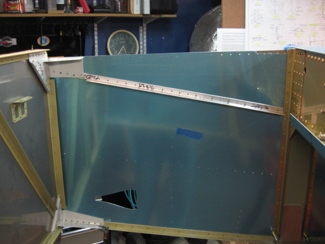
I ran into a quandary around this point. I did the entire right longeron first, then test fit it. It pretty came out per the plans (which state that the vertex should roughly parallel the bottom of the side skin with about 1/8" showing).

 Mine was 3/32", which is pretty much bang on.

From Fuselage

 After I finished the second (left) F917 I noticed that it was nearly even with the bottom edge of the skin. Only 1/32" was showing.

From Fuselage

That made me nervous.

 I know there is room for variation - it's not like we're building a watch as some folks like to say, but this is a critical juncture and an important one since we're establishing the firewall with the longerons and misalignment could do funny things (although I remeasured the firewall and it was bang on - which I expected since I measured it at least half a dozen times before drilling it).

I finally figured out the skin was a bit lower on that side and shot an email off to Van's as well as posting a question in the forums at VAF. The consensus (and my thought) was that it was fine but I wanted to check. 

Ken Scott got back with me Monday and said he saw no problems with it so I ended up drilling them to the firewall brackets Monday.

Saturday, January 19, 2013

January 20th, 2013

Managed to get everything rearranged so that I could fit the Van back in the garage. With the fuse on sawhorses for the last week or so I haven't been able to. Ran down to Harbor Freight at lunch early in the week and picked up a couple of their large moving dollies. I put the 2x4 stretchers on the saw horses to make them wider, then bungied the dollies to the saw horses. That makes the fuselage easily moveable so I can pack everything back on one side again. This week I worked on match drilling the longerons to the fuselage.  Doesn't sound like much, but it takes a while.  The longerons are 1/8" angle and 15 feet long (give or take a smidge).  There is a hole to drill about every inch. Match drilling the skins to the left longeron. The fuse is upside down at the moment, so this is the left side. The longerons are a single 15 foot section of 3/4 x 3/4 angle 1/8" thick. Takes a while to drill that much. There is one on each side.
From Fuselage
Working down the right side. Clecoes in every other hole. I then went back and drilled the in between holes. \
From Fuselage
Here's the right side done up to the F-904 bulkhead.
From Fuselage
Once it's riveted up to the 904, the longerons are trimmed to length (about 3/4" less than the skin), then the rest of the longerons are match drilled.

Monday, January 14, 2013

January 13th, 2013

With travelling, work and the holidays I didn't have a chance to do any updates to the log.  Rather than go back and try to create the missing month or so, I'll just hit the highlights.

Basically I finished up the center section, riveted it, clecoed it to the completed tail cone, added the longerons (just "slipped in place" as Van's calls it), then added the side skins and started working through the next steps.  There will be a lot of work before anything gets riveted again.

Center section:

The remaining work was mostly match drilling, deburring, cutting some holes for wiring bushings, dimpling everything and then riveting it.

Once I clecoed everything together, I decided it would be easiest to stand it vertically.  That way Becca could hold the bucking bar on one side and I could back rivet from the other with the long rivet set.  It worked well.

Before riveting.  The section is oriented nose down.  The bulkhead against the table is the aft half of the spar carrythrough (the wings will bolt to that).  The middle bulkhead that sticks out is where the seat backs will ultimately attach.  The lower ribs are where the seat bottoms will be.  The upper ribs support the baggage area.


From Fuselage
Here's the other side before we riveted.

From Fuselage

We were able to back rivet 80% or more of the rivets. Had to buck the tight spots. Becca and I were able to knock it out in about an hour. Thanks Becca!

Here is the completed center section after riveting.

From Fuselage

Here I've added the baggage and seat skins.  This stiffens the structure even more and gives you a much better idea of what it will look like.  The square holes on the lower skins are where the control sticks will eventually go.  The elevator pushrod will fit inside the open slot that goes aft from the seats.  That will be covered by a "tunnel" to protect it.

From Fuselage

This is what it will look like in the aircraft. Yes, I tried sitting on it (of course...)

From Fuselage


Once that was done it was time to mate the center section with the tail cone.

Basically everthing gets flipped upside down and supported on saw horses.  The idea is to line everything up, slide the longerons into the two sections, then cleco everything together.  There is a lot of fitting and opportunity for things to not line up very well.  I had to go at it two or three times before I could get it hooked up.  For me, the key turned out to be starting with the aft line of rivets on the bottom, then adding the side skins and start with the aft line there as well.  Once I did that it all fit very nicely.

Here it is all clecoed together - the sides haven't been added yet

From Fuselage

Everything is together and I've verified (amazingly) that the longerons were almost bang on.  Everything lines up and I'm getting ready to drill the step holes, then bend the side skin (the "shark fins" sticking up on each side) to fit the tail cone.

Bending the shark fins to fit is pretty tricky.  The forward part is almost a tight 90 degrees.  The aft part is a gentle curve.  All that is accomplished in about 12" of skin.

From Fuselage

Drilling the side skin for the boarding step.  Steps are optional (not really needed on a tail dragger).  Since mine is a tri gear I'll have them on both sides.


From Fuselage

Trimming the 623 rib to provide clearance for the step tube.


From Fuselage
One the the side skins after bending.  Hard to get everything just right on these.

From Fuselage

Unfortunately, the first skin I did (right side) ended up cracking slightly just aft of the relief hole :<.

I must have bent it a bit too far (or too often).  Stop drilling will take care of it spreading.  The step plate will be riveted over this area which will make it super strong.
\
From Fuselage